
BUNTOP / INDUSTRIAL INFRASTRUCTURE
Industrial Infrastructure & Reliability
Reliable automation depends on stable power, dependable computing and tested recovery. Plan the infrastructure supporting PLCs, HMIs, SCADA, historians, MES and edge data systems.
Prefer a simple explanation? See which machine does what ↗
Reduce the impact of power disturbances, hardware faults and production interruptions through documented dependencies, suitable protection and verified recovery procedures.
OT servers & virtual environments
Plan and maintain VMware ESXi or Microsoft Hyper-V environments according to the application vendor’s supported versions, licensing, hardware requirements and timing constraints.
- Host and edge sizing: Map dependencies, operating systems, CPU, memory, storage endurance, available capacity and cabinet conditions. Scope may range from a rugged OnLogic edge computer running supported integration services to central servers hosting SCADA, historians or MES.
- VM architecture: Separate workloads where appropriate and manage resource reservations, limits and storage performance. Separate VMs still share host resources; capacity planning addresses contention.
- Network integration: Document physical NIC assignments, virtual switches, VLANs, firewall paths, management and backup connections. Use supported NIC teaming within the same network for link resilience. Do not team across separate security zones.
- Control timing: Ethernet Layer 2 and Purdue Level 2 describe different things. Supervisory functions typically sit at Purdue Level 2, while plant operations and MES typically sit at Level 3. Direct PROFINET or EtherNet/IP I/O through virtualized hosts requires explicit application and platform support; virtual switches do not establish deterministic control timing.
- Maintenance: Monitor resource use, host health, storage, certificates and supported software versions. Test changes and coordinate patching with production windows and rollback plans.
| Deployment pattern | Engineering requirement |
|---|---|
| Single edge host | Define the local failure impact, replacement method and restore time. Multiple services on one computer share a failure point. |
| Central host cluster | Check supported failover, quorum, spare capacity, storage and network dependencies. Restarting a failed VM may interrupt service. |
| Application redundancy | Verify vendor-supported application and database replication, synchronization, failover and licensing separately from host clustering. |
Deliverables: Host and VM inventory, application dependency map, resource baseline, virtual network drawing, maintenance plan and restore records.
Backup & disaster recovery
Agree measurable recovery targets with the plant team before selecting backup and availability tools.
| Target | Meaning | Evidence |
|---|---|---|
| RTO: Recovery Time Objective | Target time to restore an agreed service after disruption | Timed restore and functional acceptance test |
| RPO: Recovery Point Objective | Acceptable data loss measured in time | Verified backup/replay points and recorded gaps |
- Use protected application-consistent backups, VM backups and host recovery methods suited to each workload. Include configuration, certificates, license recovery arrangements and dependencies.
- Keep recovery copies isolated from routine production administration where appropriate. Test that a usable copy remains available after a host failure or compromised administrator account.
- Use supported snapshots or checkpoints for short-term change rollback where appropriate. They are not complete backups, and rollback can affect application state, database consistency and external transactions.
- Document restore order, responsible owners, access requirements, spare hardware, software versions and recovery media.
- Test UPS capacity, battery condition, supported shutdown signalling and restart prerequisites. A UPS-backed shutdown requires a working end-to-end configuration.
Availability, backup and recovery address different failure scenarios. Record the outcome of each host, network, storage and application failure test.
Industrial electrical systems & control power
Engineering analysis, design review, troubleshooting, maintenance planning and documentation for low-voltage power distribution serving automated production lines.
| Supply | Typical applications | Engineering focus |
|---|---|---|
| 480 VAC, three phase | Motor control centres, VFD feeders, machine disconnects and transformer primaries | Loads, equipment ratings, fault current, short-circuit current ratings, protective-device coordination, heat and grounding |
| 120 VAC, single phase | Control transformer secondaries, selected auxiliary loads, convenience outlets and compatible computer supplies | Circuit protection, isolation, grounding/bonding arrangements, power quality and UPS sizing |
| 24 VDC | PLC power, remote I/O, instruments, safety relays and industrial switches | Branch selectivity, supply capacity, voltage drop, redundancy, buffer/DC-UPS runtime and grounding arrangement |
Supply arrangements, equipment ratings and protection are confirmed from site drawings and manufacturer data. Short-circuit current ratings and interrupting ratings address different requirements. Arc-flash assessment is a separately scoped study using the applicable site data.
- Drawing and wiring review: Reconcile field connections, schematics, panel layouts, protection ratings and cable schedules.
- Fault investigation: Trace voltage disturbances, loose connections, nuisance trips, overheating, electrical noise and grounding problems using an approved diagnostic plan.
- 24 VDC distribution: Check branch loads, startup current, supply current limiting and protection coordination so a branch fault can be isolated without unnecessary loss of healthy loads. Verify actual behaviour through an approved test.
- Modernization: Identify ageing supplies, thermal constraints, obsolete devices and unmonitored backup systems, then plan staged replacement.
Work planning: Electrical interventions use qualified personnel, site authorization and the applicable safety requirements. Plans address electrical isolation, lockout and tagout, verification of absence of voltage, stored energy and other supply sources. Apply NFPA 70E and OSHA requirements as appropriate to the work and location.
Deliverables: Schematic redlines, load and thermal review, 24 VDC distribution assessment, maintenance plan, critical spares list and commissioning records.
24 VDC protection, redundancy & bridging
Select products by function, operating conditions and required approvals. These examples identify roles rather than a site bill of materials.
| Function | Example product family | Design checks |
|---|---|---|
| Selective branch protection | Siemens SITOP PSE200U, SEL1200/SEL1400; Murrelektronik MICO | Current settings, startup demand, fault clearing, conductor protection and coordination |
| Redundant supply decoupling | Siemens SITOP PSE202U or RED1200 | Compatibility, capacity with one supply unavailable, common failures and alarm indication |
| Interruption bridging | Suitable Siemens SITOP buffer module or UPS1600 with compatible energy storage | Load, required runtime, temperature, ageing, charge state and shutdown/recovery behaviour |
Supply redundancy does not create battery runtime. Electronic branch protection does not replace all required upstream protection. Parallel operation and load sharing require supplies and wiring approved for that arrangement.
Connecting power, computing & industrial data
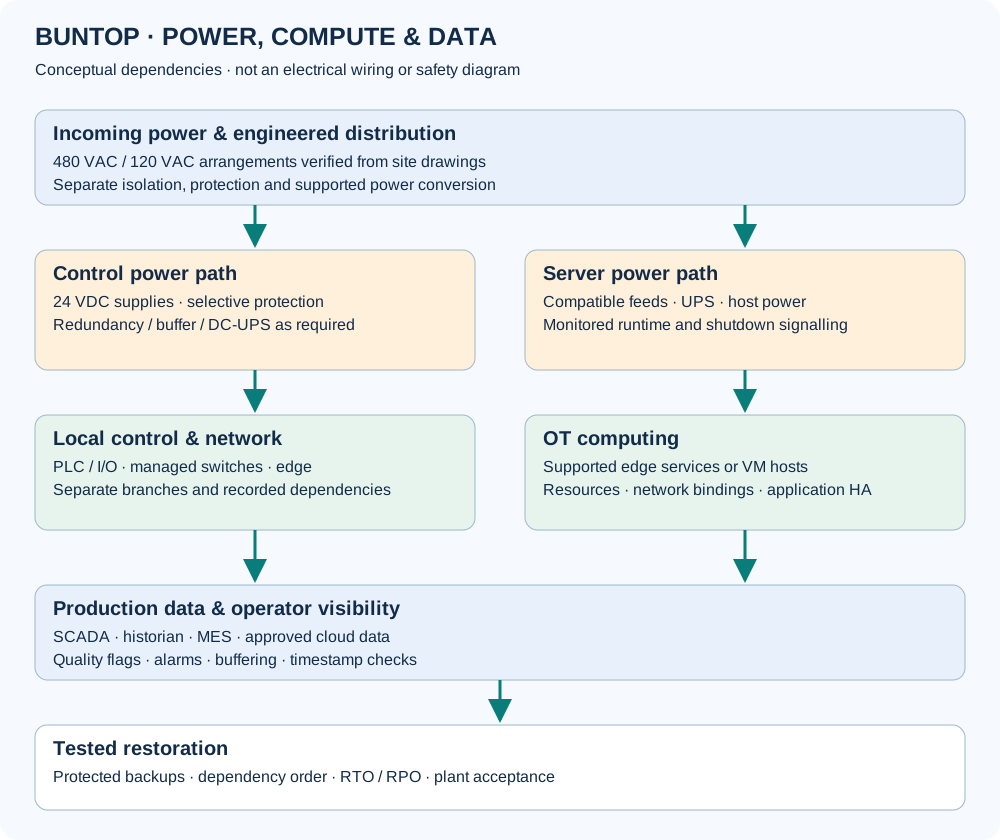
A failing 24 VDC supply can interrupt a managed switch, disconnect an edge collector and leave historian or MES screens showing stale information. The PLC may continue locally while visibility is lost. The outcome depends on the design and which equipment shares the affected supply.
Assess incoming power, control power, network connections, computing hosts, application services and data quality together.
Commissioning & handover
- Defined fault behaviour: Controls, interlocks and safety systems respond to approved requirements; power restoration does not authorize machine movement.
- Useful alarms: Power, UPS, network, host and application faults reach the appropriate team within agreed detection times.
- Controlled restoration: Services recover in a documented dependency order with acknowledgement where required.
- Data recovery: Supported buffers replay within tested capacity; identify stale values, gaps, duplicates and timestamp order.
- RTO: Measure time to restore and accept the agreed service.
- RPO: Record restored data points and any missing interval.
- Restore evidence: Capture conditions, versions, elapsed time, exceptions, owners and acceptance.
Download infrastructure review checklist
Testing that interrupts equipment or production requires an approved site plan. Recorded results demonstrate the tested conditions and limits.